Quick Start Guide
Complete walkthrough to create your first wiring harness from start to finish
Last updated: May 22, 2026
Setup Phase
Initialize your harness project
- 1
Navigate to 'Wiring Harnesses' from the dashboard
- 2
Click 'Create Wiring Harness' button
- 3
Enter a descriptive name
Use clear names like '1995 EG Civic K20 Engine Swap Harness'
- 4
Add a description (optional)
The description supports multiple lines for detailed project notes
- 5
Select your preferred measurement unit
Choose between millimeters (mm) or inches (in). You can convert units later if needed.
- 6
Click 'Create Wiring Harness' to begin

Create Wiring Harness form with name, description, and unit selection
- 1
Navigate to 'Wire Types' from the main menu
- 2
Click 'Available Wire Types' button
Located on the right side of the page just below the Wire Types Filters.
- 3
Filter by part number, gauge, or color to find specific wires
Located on the right side of the page just below the Wire Types Filters.
- 4
Select wire types using checkboxes
Select multiple wire types at once for bulk enabling
- 5
Click 'Enable Selected' to add them to your enabled list
- 6
Switch to 'Enabled Wire Types' tab to see your active wires
- 7
Create custom wire types if needed
Use 'Create Wire Type' when your exact specification isn't in the library. Custom wire types require gauge and color selection.
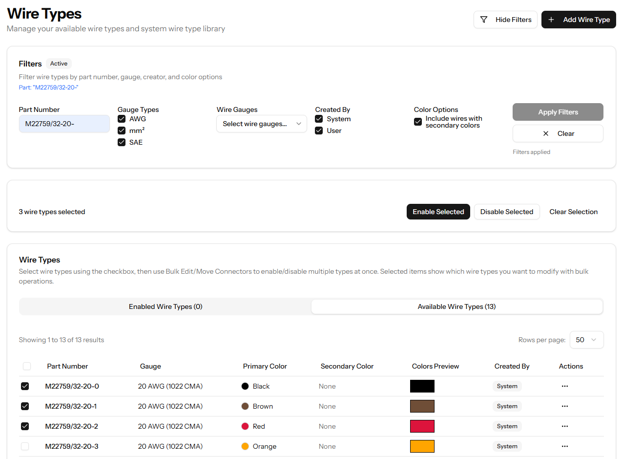
Available Wire Types with filtering options by part number, gauge, and color
- Only enabled wire types appear in connection dropdowns
- Bulk enable multiple wire types at once for efficiency
- Filter by part number to quickly find specific wire specs
Design Phase
Build your harness structure
The Device Library contains pre-configured devices from Link ECU, Haltech, MoTeC, MaxxECU, ECUMaster, Emtron, and more. Importing a device adds every connector defined on that device to your harness with cavity descriptions already filled in - no manual entry required.
Importing a device into your harness
- 1
Open your harness and navigate to the Connectors page
- 2
Click Import Device
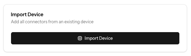
- 3
Search or filter by manufacturer and device type to find your device
Both the system library and any devices you've added yourself appear here
- 4
Click Import on the device
All connectors defined on that device are added to your harness with cavity descriptions pre-filled
- 5
Repeat for each device in your harness (ECU, PDM, sensors, etc.)
- Importing a device is far faster than creating connectors manually for any ECU, PDM, or sensor
- You can customise any system device - copy it to your personal library and rename cavities to match your naming conventions
- Can't find your device? Add it to your personal library once and import it into every future project
- Browse the full library at Device Library - no account required
After importing devices, use the manual form to add any remaining connectors: splices, ring terminals, custom sensors, or anything else not in the Device Library.
Adding a connector manually
- 1
Enter a short connector name
Examples: 'MAP', 'INJ_SUB', 'GND'
- 2
Press Tab and enter the number of cavities/pins
- 3
Press Enter to create - the form refocuses for the next connector
Creating multiple numbered connectors
Use the Create Multiple Numbered Connectors? checkbox to generate sets like INJ1–INJ4 in one step. Choose a numbering format (no space, dash, or underscore) and set a starting number if needed.
Splices and ring terminals
Scroll below the standard connector form to find dedicated sections for splices and ring terminals. Splices are auto-named (S1, S2, …) or you can enter a custom name. Ring terminals require a name such as 'RT-GND1'.
Organising with tabs
Click Add/Edit Tabs above the connector list to create named tabs (e.g. 'Injectors', 'Sensors', 'ECU'). Connectors created while a tab is active are placed in that tab automatically.
- You can also use the Connector Design Library for individual pre-configured connector designs
- Tabs help keep large harnesses with many connectors manageable
Before creating connections, add descriptions to cavities on your primary connector (like the ECU). EZ Wire's auto-propagate feature (enabled by default) will automatically copy these descriptions to connected cavities as you wire, saving significant time on documentation.
Adding Cavity Descriptions
- 1
Click in the Description field for any cavity
Each cavity row has a description field you can click to edit
- 2
Enter a descriptive label
Examples: "Injector 1 Signal", "TPS Sensor 5v+", "Coil 1 Trigger", "Chassis Ground"
- 3
Press Enter or Tab to save and move to the next cavity
The description is saved automatically
- 4
Repeat for all important cavities on your main connector
Focus on your primary connector (like the ECU) - descriptions will propagate to connected cavities automatically
Making Basic Connections
- 1
Locate the connector cavities table in your harness view
Each connector shows its cavities in a table format
- 2
Click the connection dropdown for any cavity
For example, click on the dropdown for CONN1, cavity 1
- 3
Select the destination cavity from the list
Choose the connector and cavity you want to connect to (e.g., CONN2, cavity 3)
- 4
The connection is created instantly
- 5
Click the wire type dropdown for that connection
Select from your enabled wire types
- 6
Wire gauge and color are displayed with visual color chips
- 7
Repeat for all connections in your harness

Creating wire connections between connector cavities

Selecting wire type from enabled wire types for a connection
Speed Up Wiring with the Currently Selected Wire Type
If your harness uses mostly one wire type, pre-select it in the toolbar so it's automatically filled in for every new connection.
- 1
Find the "Currently Selected Wire Type" combobox
It's in the sticky toolbar at the top of the connector list
- 2
Select your primary wire type
All new connections will have this wire type pre-filled automatically
- 3
Override per-connection if needed
You can still change the wire type on any individual connection
- 4
Clear with the × button when done
New connections will return to requiring a manual wire type choice
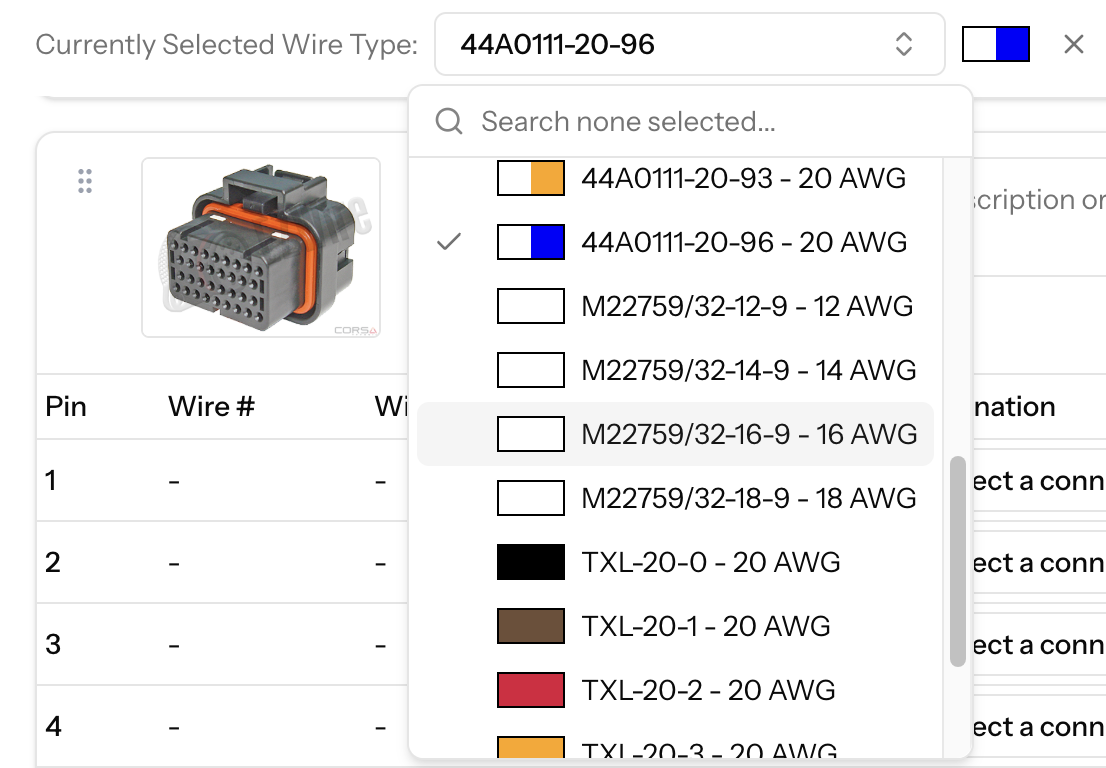
Pre-select a wire type to speed up wiring
Multiple Connections Per Cavity
Allow a single cavity to connect to multiple destinations (common for power/ground distribution)
- 1
Locate a cavity that needs multiple connections
Common example: a power splice distributing to multiple loads
- 2
Click 'Enable Multiple Connections' for that cavity
- 3
Create additional connections from the same cavity
All connections from that cavity will be listed
- 4
Each connection can use a different wire type
- Only unconnected cavities appear in the connection dropdown
- Setting a cavity to 'No Connection' removes it from the connection dropdown
- You can connect across tabs, all connectors are available
- Smart Documentation: Add cavity descriptions to your main connector (like the ECU) before creating connections. Cavity description propagation (enabled by default) will automatically copy these descriptions to connected cavities as you wire, saving significant time on documentation.
The Visual Diagram is where you build the physical layout of your harness. Branches, lengths between connectors and branches, and splice positioning are all handled here on the interactive canvas. Positions are saved automatically so you can return and adjust at any time.
- 1
Click 'Visual Diagram' from your harness menu
All connectors you've defined will appear on the canvas ready to arrange
- 2
Drag connectors to arrange your harness layout
Click and drag from the centre of any node. Moving a connector also moves its attached image and label.
- 3
Draw lengths between connectors and branches
Hover the edge of a connector or branch until the arrow icon appears, then drag to another node. A pop-up will ask for the length value before it is saved. Add bends by clicking along a length line.
- 4
Position splices by merging splice nodes
Drag one splice on top of another to merge them - an orange highlight confirms the drop point. Merged splices can be split again by right-clicking and selecting Split Node.
- 5
Resize or hide connector images using right-click
Click a connector image to reveal resize handles. Right-click for options to hide, restore, or change the image view.
- 6
Use Page Setup to choose a canvas size, then export to PDF
Use the toolbar controls to set the page size and zoom, then click the export button to download a PDF.
- Connector images and labels can be moved independently of the connector circle for fine-tuning
- Toggle measurements on/off (SHOP/PRO) when sharing the diagram externally
- A connector can only have one length assigned to it - use branches when wires split to multiple destinations
Finalize Phase
Complete and export your harness
Before finalizing your harness, configure important settings that affect how your harness behaves and how documentation is generated.
- 1
Click the Settings button at the top of your harness page
Located next to the Print button in the harness header
- 2
Review and adjust measurement units if needed
Convert between millimeters (mm) and inches (in) - all lengths and cut list values will be converted
- 3
Verify "Auto-propagate cavity descriptions" is enabled
This feature is enabled by default. When active, creating a connection automatically copies cavity descriptions between connected cavities if one has a description and the other doesn't. This ensures consistent documentation throughout your harness. You can disable it if you prefer to manage descriptions manually.
- Cavity description propagation is enabled by default to save time documenting cavities
- The Settings menu also allows you to duplicate or delete the entire harness
- Measurement unit conversion is non-destructive and can be changed at any time
- 1
Navigate to your Cut List
- 2
Click 'Edit Idents' to enter edit mode
- 3
Click 'Columns' > 'All Details' to see all ident columns
- 4
Add up to 5 color bands in 3 positions for each wire
• Overall: identification for the entire wire• From end: colors near the starting connector• To end: colors near the destination connector - 5
Type numbers 0-9 representing colors
0=Black, 1=Brown, 2=Red, 3=Orange, 4=Yellow, 5=Green, 6=Blue, 7=Violet, 8=Gray, 9=WhiteVisual color previews appear as you type
- 6
Press Tab to move between fields, Enter to save and move to next wire
- 7
Click 'Finish Editing Idents' when done
- Wire idents use MIL-STD-681F color coding system (0-9)
- Maximum 5 bands per position
- Color bands help with installation and troubleshooting
- 1
In your Cut List, click the settings button
- 2
Configure additional length to add to each wire
Accounts for routing slack and connector entry
- 3
Set rounding precision
For example, round up to nearest 10mm or 0.5 inches
- 4
Choose column visibility with 'Columns' dropdown
• Essential: wire number, from/to, wire type, length• All Details: includes idents, colors, strip lengths - 5
Reorder wires using the drag handles if needed
Click 'Update Sort Order' to save custom wire ordering
- 6
Use 'Edit Twisted Pairs' to mark wires that run together
Helps installers know which wires to twist together
- Rounding helps standardize wire lengths for easier cutting
- Custom sort order affects wire numbering
- Twisted pairs notation helps installers identify paired wires
- Settings are saved per harness
- 1
Click 'Bill of Materials' from your harness menu
- 2
Review all components and their quantities
• Connectors with part numbers and quantities• Wire types with total length needed per type• Splices and ring terminals - 3
Quantities are automatically calculated from your design
- 4
Export the BOM for ordering or sharing
- BOM updates automatically as you modify the harness
- Wire lengths are totaled by type across all connections
- Use this to generate purchase orders
- Part numbers you entered appear here for easy reference
- 1
Use the Print button at the top of each page
Note: Browser shortcuts (Ctrl+P/Cmd+P) are disabled. Always use the Print button provided in the interface.
- 2
Print connector pinouts from the main harness page
• Cavity numbers and connection destinations• Wire types and colors• Print individual tabs or the entire harness - 3
Print the Cut List with customizable settings
• Configure length calculations before printing• All settings must be saved before printing• Toggle column visibility for minimal or detailed views• Choose landscape or portrait orientation - 5
Share documentation with your assembly team
All prints are optimized for production use with clean, professional layouts
- Always save Cut List settings before printing to ensure accurate wire lengths
- Use landscape orientation for Cut Lists with many columns
- Print connector pinouts in color to easily identify wire color idents
- Export BOM to CSV for easy integration with purchasing systems
- Print specific tabs when working on harness sections separately