
Connections Guide
Complete guide to creating and managing wire connections in EZ Wire
Last updated: September 30, 2026
- Connectors created with cavities to connect
- Wire types enabled from the parts library
Once you have connectors and enabled wire types, you can create connections between connector cavities. Each connection represents a physical wire in your harness.
Creating a Connection
- 1
Open Connection Dropdown
In your wiring harness view, each connector displays its cavities in a table. Click the connection dropdown for any cavity (e.g., click "Select a connection" for CONN1 cavity 1).
- 2
Select Destination Cavity
Choose where this cavity connects to from the dropdown list. You'll see all available unconnected cavities from all connectors across all tabs (e.g., CONN2.3, SENSOR1.1, SP-POWER).
- 3
Select Wire Type
Click the wire type dropdown for the connection. Select from your enabled wire types, or start typing to search the full wire type library — picking a searched result enables it for you automatically, so you never have to leave the harness page to activate a new one. If nothing matches, click "Create wire type" to add a brand new one on the spot. The gauge and color are displayed with visual color chips for easy identification.
- 4
Visual Confirmation
Once selected, the connection shows the destination and wire type (e.g., "CONN2.3 - 20 AWG Black") with color visualization.
The sticky toolbar at the top of the connector list gives you two controls that apply across all connectors in the harness: a wire type pre-selector and a global cavity expand/collapse toggle.
Currently Selected Wire Type
Use the Currently Selected Wire Type combobox to choose a wire type once at the harness level. Whenever you add a new connection to any cavity, that wire type is automatically pre-filled in the wire type field - saving you from selecting it individually for every connection.
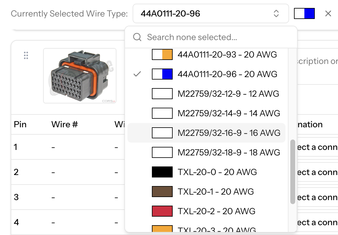
The "Currently Selected Wire Type" combobox in the connector toolbar
- 1
Open the wire type combobox
Click the "Currently Selected Wire Type" dropdown in the toolbar. It shows all wire types enabled for this harness, with their part number, gauge, and a color preview.
- 2
Select a wire type
Choose the wire type you want to use for upcoming connections. A color preview appears next to the combobox as a quick visual reference.
- 3
Create connections as normal
New connections across any connector will have the selected wire type pre-filled. You can still override it on a per-connection basis.
- 4
Clear the selection when done
Click the × button beside the combobox to clear the pre-selection. New connections will return to requiring a manual wire type choice.
Show / Hide All Cavities
The Show All Cavities / Hide All Cavities button on the right side of the toolbar expands or collapses the cavity rows for every connector at once. This is useful when you want a high-level overview of all connectors without scrolling through every cavity row.
Go to the Other End of a Connection
Each connected cavity has an arrow button to the right of its Destination dropdown. Click it to jump to the cavity at the other end of the wire. EZ Wire expands that connector, scrolls to the cavity and briefly highlights it. If the other end is on a different tab, it switches to that tab first.
To hide the arrows, click the arrow icon in the Destination column header. This applies to every connector, and your browser remembers the choice.
By default, each cavity can only have one connection. For power distribution, ground splices, or any junction where multiple wires connect to one point, enable multiple connections.
Enabling Multiple Connections
- 1
Locate the Cavity
Find the cavity that needs to connect to multiple destinations (typically a splice or power junction).
- 2
Click "Enable Multiple Connections"
Click the button next to the cavity. The cavity can now have more than one connection.
- 3
Create Additional Connections
Add multiple connections from the same cavity. Each connection appears in the table and can use a different wire type.
- 4
Disable if Needed
To disable multiple connections, click "Disable Multiple Connections". You must first reduce to one or zero connections.
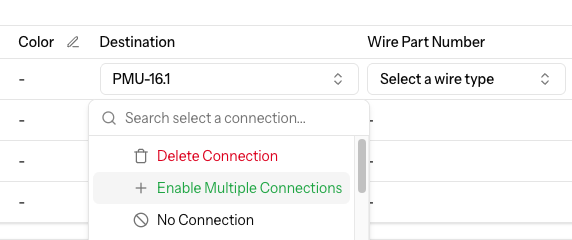
A cavity with multiple connections enabled
Sometimes connectors have cavities that remain empty or unused. Use the "No Connection" status to indicate these intentionally unconnected cavities.

Setting No Connection
- 1
Open Connection Dropdown
Click the connection dropdown for the cavity you want to mark as unused.
- 2
Select "No Connection"
Choose "No Connection" from the dropdown. The cavity row will be grayed out to indicate it's not in use.
- 3
Cavity Becomes Unavailable
Once marked as "No Connection", this cavity will no longer appear in other cavities' connection dropdowns.
- 4
Clear if Needed
To clear "No Connection", click the X button that appears. The cavity becomes available again.
EZ Wire automatically propagates cavity descriptions between connected cavities. This feature is enabled by default. When you create a connection and one cavity has a description while the other doesn't, the description is automatically copied to the empty cavity.
Managing the Setting
- 1
Click the Settings (gear) button in the toolbar above the connector list
Located next to the Print and Labels buttons. On small screens it is in the ⋯ menu
- 2
Check or uncheck "Auto-propagate cavity descriptions"
The checkbox will be checked by default. Uncheck it to disable automatic propagation.
- 3
The setting saves automatically
Your preference is saved immediately when you toggle the checkbox
For more details about harness settings and configuration options, see the Wiring Harnesses Guide.
Once you've added a cable to the harness from your cable type library, each of its conductors becomes selectable in the wire type dropdown when you build a connection.
- Conductors are listed by their conductor name (for example
CAM-M22759/32-20-9) and marked with a Cable badge so they're easy to tell apart from ordinary wire types. - A conductor can only be used once. As soon as it's connected it drops out of the list, so you can't run the same cable conductor twice by accident.
- Conductors don't appear as separate wires on the cut list - they're listed under their cable, and the cable is cut to the length of its longest conductor run.
When a harness contains a shielded cable, its shield appears as a connection target in the destination dropdown, listed alongside the other cavities. Select it to terminate a cavity at the shield - for example, tying a drain wire to ground.
- The wire type column shows the shield's name (for example
CAM-SHIELD) as a disabled value - the shield itself is the wire type, so there is nothing to pick. - Any number of cavities can connect to the same shield.
- Shield connections are excluded from the cut list and wire-length calculations, since they are not cut wires.
You can easily modify connections after they've been created, whether you need to change the destination or select a different wire type.
How to Change Connections
Changing the Wire Type
Click the wire type dropdown for an existing connection and select a different wire type. The connection destination stays the same, only the wire specification changes.
Changing the Destination
Click the connection dropdown (where the destination is shown) and select a different cavity. The previous destination becomes available again for other connections.
Deleting a Connection
Click the X button next to a connection to delete it entirely. Both cavities become available for new connections.
Clearing All Connections on a Connector
Open a connector's Actions menu and choose Clear All Connections to remove every connection on that connector at once. The connector and its cavities stay in place - only the wires connecting them are removed. This action cannot be undone.
Enable Wire Types First
Enable the wire types you'll need before creating connections to streamline your workflow.
Pre-Select a Wire Type in the Toolbar
Use the "Currently Selected Wire Type" combobox in the connector toolbar to pre-fill the wire type for all new connections. This is especially effective when a harness predominantly uses a single wire type.
Use Cavity Description Propagation
Enable auto-propagate cavity descriptions in Settings to automatically copy descriptions between connected cavities, ensuring consistent documentation throughout your harness.
Mark Unused Cavities
Use "No Connection" for intentionally empty cavities to keep your design organized and prevent confusion.
Review Connection List
Regularly review your connections to ensure all cavities are wired correctly and no connections are missing.
Use Appropriate Wire Gauges
Select wire gauges appropriate for the current requirements. Power connections typically need heavier gauge wires.